TransportPCE Developer Guide {#transportpce-dev-guide}
Overview
TransportPCE describes an application running on top of the OpenDaylight controller. Its primary function is to control an optical transport infrastructure using a non-proprietary South Bound Interface (SBI). It may be interconnected with Controllers of different layers (L2, L3 Controller...), a higher layer Controller and/or an Orchestrator through non-proprietary Application Programing Interfaces (APIs). Control includes the capability to configure the optical equipment, and to provision services according to a request coming from a higher layer controller and/or an orchestrator. This capability may rely on the controller only or it may be delegated to distributed (standardized) protocols.
Architecture
TransportPCE modular architecture is described on the next diagram. Each main function such as Topology management, Path Calculation Engine (PCE), Service handler, Renderer _responsible for the path configuration through optical equipment_ and Optical Line Management (OLM) is associated with a generic block relying on open models, each of them communicating through published APIs.
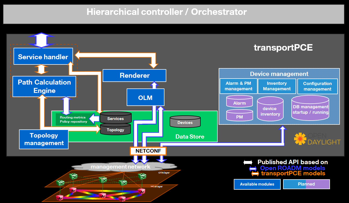
The current version of transportPCE is dedicated to the control of WDM transport infrastructure. OTN layer will be integrated in a later step. The WDM layer is built from colorless ROADMs and transponders.
The interest of using a controller to provision automatically services strongly relies on its ability to handle end to end optical services that spans through the different network domains, potentially equipped with equipment coming from different suppliers. Thus, interoperability in the optical layer is a key element to get the benefit of automated control.
Initial design of TransportPCE leverages Open ROADM Multi-Source-Agreement (MSA) which defines interoperability specifications, consisting of both Optical interoperability and Yang data models.
Module description
ServiceHandler
Service Handler handles request coming from a higher level controller or an orchestrator through the northbound API, as defined in the Open ROADM service model. Current implementation addresses the following rpcs: service-create, service--delete, service-reroute. It checks the request consistency and trigs path calculation sending rpcs to the PCE. If a valid path is returned by the PCE, path configuration is initiated relying on Renderer and OLM. At the confirmation of a successful service creation, the Service Handler updates the service-list in the MD-SAL. For service deletion, the Service Handler relies on the Renderer and the OLM to delete connections and reset power levels associated with the service. The service-list is updated following a successful service deletion.
PCE
The Path Computation Element (PCE) is the component responsible for path calculation. An interface allows the Renderer or external components such as an orchestrator to request a path computation and get a response from the PCE including the computed path(s) in case of success, or errors and indication of the reason for the failure in case the request cannot be satisfied. Additional parameters can be provided by the PCE in addition to the computed paths if requested by the client module. An interface to the Topology Management module allows keeping PCE aligned with the latest changes in the topology. Information about current and planned services is available in the MD-SAL data store.
Current implementation of PCE allows finding the shortest path, minimizing either the hop count (default) or the propagation delay. Wavelength is assigned considering a fixed grid of 96 wavelengths. Current PCE handles the following constraints as hard constraints:
- Node exclusion
- SRLG exclusion
- Maximum latency
Topology Management
Topology management module builds the Topology according to the Network model defined in OpenROADM. The topology is aligned with I2RS model. It includes several network layers:
- CLLI layer corresponds to the locations that host equipment
- Network layer corresponds to a first level of disaggregation where we separate Xponders (transponder, muxponders or switchponders) from ROADMs
- Topology layer introduces a second level of disaggregation where ROADMs Add/Drop modules (\"SRGs\") are separated from the degrees which includes line amplifiers and WSS that switch wavelengths from one to another degree
OTN layer which includes OTN elements having or not the ability to switch OTN containers from client to line cards is not currently implemented.
Renderer
The Renderer module, on request coming from the Service Handler through a service-implementation-request /service delete rpc, sets/deletes the path corresponding to a specific service between A and Z ends. It first checks what are the existing interfaces on the ports of the different nodes that the path crosses. It then creates missing interfaces. After all needed interfaces have been created it sets the connections required in the nodes and notifies the Service Handler on the status of the path creation. Path is created in 2 steps (from A to Z and Z to A). In case the path between A and Z could not be fully created, a rollback function is called to set the equipment on the path back to their initial configuration (as they were before invoking the Renderer).
OLM
Optical Line Management module implements two main features: it is responsible for setting up the optical power levels on the different interfaces, and is in charge of adjusting these settings across the life of the optical infrastructure.
After the different connections have been established in the ROADMS, between 2 Degrees for an express path, or between a SRG and a Degree for an Add or Drop path; meaning the devices have set WSS and all other required elements to provide path continuity, power setting are provided as attributes of these connections. This allows the device to set all complementary elements such as VOAs, to guaranty that the signal is launched at a correct power level (in accordance to the specifications) in the fiber span. This also applies to X-Ponders, as their output power must comply with the specifications defined for the Add/Drop ports (SRG) of the ROADM. OLM has the responsibility of calculating the right power settings, sending it to the device, and check the PM retrieved from the device to verify that the setting was correctly applied and the configuration was successfully completed.
Key APIs and Interfaces
External API
North API, interconnecting the Service Handler to higher level applications relies on the Service Model defined in the MSA. The Renderer and the OLM are developed to allow configuring Open ROADM devices through a southbound Netconf/Yang interface and rely on the MSA's device model.
ServiceHandler Service
- RPC call
- service-create (given service-name, service-aend, service-zend)
- service-delete (given service-name)
- service-reroute (given service-name, service-aend, service-zend)
- Data structure
- service list : composed of services
- service : composed of service-name, topology wich describes the detailed path (list of used resources)
- Notification
- service-rpc-result : result of service RPC
- service-notification : service has been added, modified or removed
Netconf Service
- RPC call
- connect-device : PUT
- disconnect-device : DELETE
- check-connected-device : GET
- Data Structure
- node list : composed of netconf nodes in topology-netconf
Internal APIs
Internal APIs define REST APIs to interconnect TransportPCE modules :
- Service Handler to PCE
- PCE to Topology Management
- Service Handler to Renderer
- Renderer to OLM
Pce Service
- RPC call
- path-computation-request (given service-name, service-aend, service-zend)
- cancel-resource-reserve (given service-name)
- Notification
- service-path-rpc-result : result of service RPC
Renderer Service
- RPC call
- service-implementation-request (given service-name, service-aend, service-zend)
- service-delete (given service-name)
- Data structure
- service path list : composed of service paths
- service path : composed of service-name, path description giving the list of abstracted elements (nodes, tps, links)
- Notification
- service-path-rpc-result : result of service RPC
Topology Management Service
- Data structure
- network list : composed of networks(openroadm-topology, netconf-topology)
- node list : composed of node-id
- link list : composed of link-id
- node : composed of roadm, xponder link : composed of links of different types (roadm-to-roadm, express, add-drop ...)
OLM Service
- RPC call
- get-pm (given node-id)
- service-power-setup
- service-power-turndown
- service-power-reset
- calculate-spanloss-base
- calculate-spanloss-current
Running transportPCE project
To use transportPCE controller, the first step is to connect the controller to optical nodes through the NETCONF connector.
::: {.note} ::: {.admonition-title} Note :::
In the current version, only optical equipment compliant with open ROADM datamodels are managed by transportPCE. :::
Connecting nodes
To connect a node, use the following JSON RPC
REST API : POST /restconf/config/network-topology:network-topology/topology/topology-netconf/node/\<node-id>
Sample JSON Data
``` {.sourceCode .json}
{
"node": [
{
"node-id": "
1 2 3 4 5 6 7 8 9 10 11 12 13 14 15 16 17 18 19 20 21 22 23 24 25 26 27 28 29 30 31 32 33 34 35 36 37 38 39 40 41 42 43 44 45 46 47 48 49 50 51 52 53 54 55 56 57 58 59 60 61 62 63 64 65 66 67 68 69 70 71 72 73 74 75 76 77 78 79 | Then check that the netconf session has been correctly established
between the controller and the node. the status of
**netconf-node-topology:connection-status** must be **connected**
**REST API** : *GET
/restconf/operational/network-topology:network-topology/topology/topology-netconf/node/\<node-id\>*
### Node configuration discovery
Once the controller is connected to the node, transportPCE application
automatically launchs a discovery of the node configuration datastore
and creates **Logical Connection Points** to any physical ports related
to transmission. All *circuit-packs* inside the node configuration are
analyzed.
Use the following JSON RPC to check that function internally named
*portMapping*.
**REST API** : *GET /restconf/config/portmapping:network*
::: {.note}
::: {.admonition-title}
Note
:::
In `org-openroadm-device.yang`, two types of optical nodes can be managed:
: - rdm: ROADM device (optical switch)
- xpdr: Xponder device (device that converts client to optical
channel interface)
:::
Depending on the kind of open ROADM device connected, different kind of
*Logical Connection Points* should appear, if the node configuration is
not empty:
- DEG\<degree-number\>-TTP-\<port-direction\>: created on the line
port of a degree on a rdm equipment
- SRG\<srg-number\>-PP\<port-number\>: created on the client port of a
srg on a rdm equipment
- XPDR\<number\>-CLIENT\<port-number\>: created on the client port of
a xpdr equipment
- XPDR\<number\>-NETWORK\<port-number\>: created on the line port of a
xpdr equipment
> For further details on openROADM device models, see [openROADM MSA
> white
> paper](https://0201.nccdn.net/1_2/000/000/134/c50/Open-ROADM-MSA-release-2-Device-White-paper-v1-1.pdf).
### Optical Network topology
Before creating an optical connectivity service, your topology must
contain at least two xpdr devices connected to two different rdm
devices. Normally, the *openroadm-topology* is automatically created by
transportPCE. Nevertheless, depending on the configuration inside
optical nodes, this topology can be partial. Check that link of type
*ROADMtoROADM* exists between two adjacent rdm nodes.
**REST API** : *GET
/restconf/config/ietf-network:network/openroadm-topology*
If it is not the case, you need to manually complement the topology with
*ROADMtoROADM* link using the following REST RPC:
**REST API** : *POST /restconf/operations/networkutils:init-roadm-nodes*
**Sample JSON Data**
``` {.sourceCode .json}
{
"networkutils:input": {
"networkutils:rdm-a-node": "<node-id-A>",
"networkutils:deg-a-num": "<degree-A-number>",
"networkutils:termination-point-a": "<Logical-Connection-Point>",
"networkutils:rdm-z-node": "<node-id-Z>",
"networkutils:deg-z-num": "<degree-Z-number>",
"networkutils:termination-point-z": "<Logical-Connection-Point>"
}
}
|
\<Logical-Connection-Point> comes from the portMapping function.
Unidirectional links between xpdr and rdm nodes must be created manually. To that end use the two following REST RPCs:
From xpdr to rdm:
REST API : POST /restconf/operations/networkutils:init-xpdr-rdm-links
Sample JSON Data
``` {.sourceCode .json}
{
"networkutils:input": {
"networkutils:links-input": {
"networkutils:xpdr-node": "
1 2 3 4 5 6 7 8 9 10 11 12 13 14 15 16 17 18 19 20 | #### From rdm to xpdr:
**REST API** : *POST
/restconf/operations/networkutils:init-rdm-xpdr-links*
**Sample JSON Data**
``` {.sourceCode .json}
{
"networkutils:input": {
"networkutils:links-input": {
"networkutils:xpdr-node": "<xpdr-node-id>",
"networkutils:xpdr-num": "1",
"networkutils:network-num": "<xpdr-network-port-number>",
"networkutils:rdm-node": "<rdm-node-id>",
"networkutils:srg-num": "<srg-number>",
"networkutils:termination-point-num": "<Logical-Connection-Point>"
}
}
}
|
Creating a service
Use the following REST RPC to invoke service handler module in order to create a bidirectional end-to-end optical connectivity service between two xpdr over an optical network composed of rdm nodes.
REST API : POST /restconf/operations/org-openroadm-service:service-create
Sample JSON Data
``` {.sourceCode .json}
{
"input": {
"sdnc-request-header": {
"request-id": "request-1",
"rpc-action": "service-create",
"request-system-id": "appname"
},
"service-name": "test1",
"common-id": "commonId",
"connection-type": "service",
"service-a-end": {
"service-rate": "100",
"node-id": "
1 2 3 4 5 6 7 8 9 10 11 12 13 14 15 16 17 18 19 20 21 22 23 24 25 26 27 28 29 30 | Most important parameters for this REST RPC are the identification of
the two physical client ports on xpdr nodes.This RPC invokes the *PCE*
module to compute a path over the *openroadm-topology* and then invokes
*renderer* and *OLM* to implement the end-to-end path into the devices.
### Deleting a service
Use the following REST RPC to invoke *service handler* module in order
to delete a given optical connectivity service.
**REST API** : *POST
/restconf/operations/org-openroadm-service:service-delete*
**Sample JSON Data**
``` {.sourceCode .json}
{
"input": {
"sdnc-request-header": {
"request-id": "request-1",
"rpc-action": "service-delete",
"request-system-id": "appname",
"notification-url": "http://localhost:8585/NotificationServer/notify"
},
"service-delete-req-info": {
"service-name": "test1",
"tail-retention": "no"
}
}
}
|
Most important parameters for this REST RPC is the service-name.
Help
- TransportPCE Wiki
- TransportPCE Mailing List (developer)